car hydraulic brake system, car brake pedals, auto brake push rods, car brake control modules, auto master cylinders, car brake oil tanks, car brake lines, auto brake caliper

How does a car’s hydraulic brake system work?

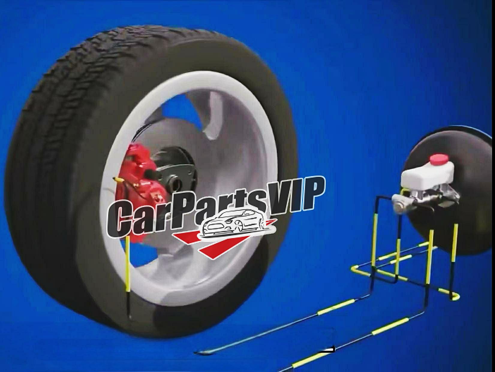
A speeding car can stop immediately by stepping on the brakes when it encounters an emergency. So what principle does the car use to brake and stop? In modern cars, the hydraulic brake system is the most commonly used brake system, which is what we often call the brake system. The principle of hydraulic braking is to seal the liquid in the brake line without air. Because the liquid cannot be compressed and can transmit power 100%, when the liquid is pressurized, the liquid transmits the pressure through the pipeline to the piston of the brake caliper of each wheel. The piston drives the brake caliper to clamp the brake pad, thereby generating huge friction to slow down the vehicle. Since the liquid can bend without being affected by the pipeline route, hydraulic braking is currently the most effective braking solution.

So what parts does the automobile hydraulic brake system use to achieve braking? First of all, there are brake pedals, brake push rods, brake control modules installed in iron boxes, master cylinders, brake oil tanks, and brake lines. When the driver steps on the brake pedal, mechanical force is transmitted to the brake push rod, which transmits power to the brake control module. The control module converts the mechanical force into vacuum liquid pressure and transmits it to the sealed master cylinder. The piston in the master cylinder pushes the brake oil to the four brake lines under the action of hydraulic pressure. When the pressure is released, the brake oil returns to the master cylinder. There must be enough brake oil in the tank to prevent it from entering the hydraulic system. When the wheel brakes, the brake pedal is stepped on. The brake control module converts the mechanical force into liquid pressure and pressurizes it, causing the brake oil in the master cylinder to flow to each brake line. The pressure of the brake oil is transmitted to the piston of each wheel brake caliper through the pipeline. The piston drives the brake caliper to clamp the brake disc and slow down the wheel. When the brake pedal is released, the brake oil returns to the master cylinder, the piston of the wheel brake caliper is released, and the wheel starts to turn again. This is the working principle of the hydraulic brake system.

car hydraulic brake system, car brake pedals, auto brake push rods, car brake control modules, auto master cylinders, car brake oil tanks, car brake lines, auto brake caliper

auto disc brake system, auto wheel hub assembly, auto disc brake, auto brake caliper, car wheel nut, auto brake pad, auto wheel bearing hub, How do brake pads stop the car, Brake pad replacement frequencyauto disc brake system, auto wheel hub assembly, auto disc brake, auto brake caliper, car wheel nut, auto brake pad, auto wheel bearing hub, How do brake pads stop the car, Brake pad replacement frequency

How does a disc brake system stop the wheels and stop the car?

The disc brake system is controlled by hydraulic pressure. Its working principle is to convert mechanical power into liquid pressure, and then the hydraulic pressure creates a huge friction force to slow down the wheel. The friction force is converted into heat energy, which is finally dissipated into the air. At present, hydraulic disc brake systems are widely used in family cars.

What are the components and functions of a disc brake system?

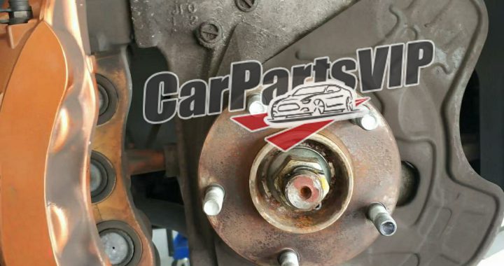
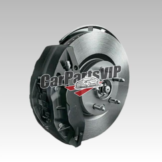
A typical disc brake system consists of the following components: wheel hub assembly, brake disc, brake caliper, wheel, and wheel nut. The wheel hub assembly is connected to the chassis of the car and also serves to fix the brake disc and other components. There is a bearing in the wheel hub assembly, which can control the wheel to make it rotate smoothly. The brake disc is an important component. It consists of two metal discs, one of which is equipped with a heat dissipation system. Because when braking, the friction between the brake pad and it will generate huge friction, and the huge friction will generate high temperature, especially on a long downhill. If the downhill speed is not controlled, the brake disc is easy to burn red. The heat dissipation system can accelerate air circulation and play a role in cooling and exhaust. The brake caliper is the main braking component. It can squeeze the brake pad through pressure so that the brake pad can stop the brake disc. It generally consists of a hydraulic piston, a bracket and a brake pad component. When we step on the pedal, the brake oil flows into the hydraulic piston in the brake caliper through the brake pipe under the pressure of the hydraulic brake system. The piston is squeezed out, and when the brake pedal is released, the piston returns to its original position. There is a sealing ring on the outside of the piston, which can prevent dust and dirt and protect the piston. Let’s look at the bracket component. It is generally installed on the car wheel hub to fix the brake pad and the caliper body. The piston assembly can be moved after the sliding pin is inserted. The brake pad is composed of four parts. The gasket reduces vibration and noise. The back plate is the rigid basis of the friction material. The interlayer between the back plate and the friction material plays a bonding role, which is responsible for bonding the friction material and the back plate together, and can also play a role in heat insulation. Finally, there is the friction material made of various compounds. It must have the characteristics of wear resistance, heat resistance, high strength and long life. The two brake pads are installed on the bracket and fixed by spring cuts. The brake pads are used very frequently and need to be replaced in time after wear, otherwise it will affect the braking performance.

How does a disc brake system work?

The working principle of the disc brake system: When the driver steps on the brake pedal, the mechanical force is converted into liquid pressure. The hydraulic pressure forces the brake oil to enter the piston assembly. The piston is pushed out to press the inner brake pad against the brake disc. Under the influence of friction, the brake disc begins to slow down. Since the inner brake pad can no longer move, no further pressure can be applied. When the hydraulic system continues to increase pressure, it will force the brake caliper body to move backward along the bearing. At this time, the outer brake pad begins to work. Under the joint action of the brake pads on both sides, the brake disc is stopped and the wheel stops rotating. When the brake pedal is released, the pressure is released and the piston returns to its original position.

How often do brake pads need to be replaced?

Brake pads generally need to be replaced after 3-5 km for front brake pads and 6-8 km for rear brake pads, but each car owner has different braking habits, so it depends on the actual wear and tear. Generally, the thickness of a new brake pad is about 1-1.5 cm. As the number of times increases, the thickness of the brake pad gradually becomes thinner, and the limit of use is 3 mm. If the thickness of the brake pad is only about 1/3 of the original thickness (about 0.5 cm), the brake pad needs to be replaced. When stepping on the brake, it is obvious that the brake is weak and soft. It is necessary to step on the brake deeply to achieve the previous braking effect. At this time, the braking distance becomes longer, which seriously affects driving safety and requires the replacement of brake pads.

auto disc brake system, auto wheel hub assembly, auto disc brake, auto brake caliper, car wheel nut, auto brake pad, auto wheel bearing hub, How do brake pads stop the car, Brake pad replacement frequency


auto wheel hub, auto wheel hub bearing, auto steering knuckle, auto suspension links, car beams, auto brake disc, auto brake caliper, auto ball joint, auto anti-roll bar , auto rubber bushings

The structure and working principle of the suspension system

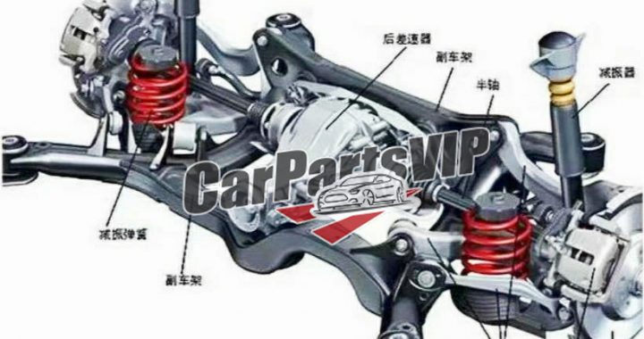
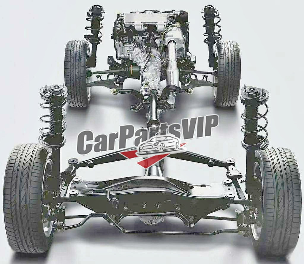
Let’s take independent suspension as an example to learn more about the structure and working principle of the suspension. The most typical independent suspensions are the McPherson suspension system, double wishbone suspension, and multi-link suspension. The suspension system includes the wheel hub assembly, suspension links, control arms and beams, springs, shock absorbers, lateral balance bars (anti-roll bars), suspension mounting elements and other components. First of all, the entire wheel hub assembly consists of the wheel hub, wheel hub bearing, and steering knuckle. The wheel hub is installed on the steering knuckle. The steering knuckle is also called the horn. It has a wheel hub bearing inside. After the three are connected, they are connected to the control arm through the steering knuckle. The wheel hub is connected to the brake disc and the wheel. The steering knuckle is connected to the tie rod in addition to the control arm. In addition, the brake caliper is also installed on the steering knuckle. When the steering wheel turns, it drives the steering knuckle to move, and then drives the tie rod to move. The tie rod drives the steering knuckle to move, so that the wheel rotates to realize the steering function. Next is the suspension link, control arm and beam. In order to enable the wheels to move within a controllable range, each link, control arm and beam are indispensable. These components can also transmit the horizontal and longitudinal forces from the road surface.

Let’s continue to look at the coil spring and shock absorber. The two of them are combined to form a shock absorber pillar, which supports the weight of the vehicle body. When there is an external force pressing down, it will compress and deform, and when the external force is released, it will return to its original state. Therefore, the role of the coil spring is to absorb the vertical force of the downward pressure during the compression stroke of the vehicle body to mitigate the impact. In addition to coil springs, there are torsion bar springs, leaf springs and air springs. The torsion bar spring is a metal rod that can be twisted. It is rare in modern cars, but it often appears in many tracked vehicles. It can achieve a torsion effect. The leaf spring should be very common. It is made of stacked multiple steel plates. It is often seen in many cars and trucks. Its characteristics are strong bearing capacity but very hard. The air spring is a compressed gas filled in a sealed container, and the compressible characteristics of the gas are used to achieve elasticity. The pneumatic suspension system with air springs has good ride comfort, but due to its complex design and high manufacturing cost, it is generally used in high-end cars. Let’s look at the shock absorber. The role of the shock absorber is to suppress the rebound of the vehicle body and play a damping role. When the coil spring is pressed down and the external force is released, the spring will rebound several times after returning to its original state. These rebound actions are the characteristics of the spring component itself. If shock absorbers are not used to prevent the coil spring from rebounding, the vehicle will continue to shake vertically up and down when passing through the shock absorber belt. Therefore, the role of the shock absorber is to suppress the rebound during the extension stroke of the suspension and allow the vehicle to quickly restore balance.

Let’s look at the lateral balance bar, also called the anti-roll bar. The function of the anti-roll bar is to prevent the vehicle from rolling when turning. It is a U-shaped metal rod. Its central part is fixed to the subframe by a rubber bushing, and its two ends are connected to the suspension through two connecting rods. When the wheels on both sides pass through uneven roads at the same time, the anti-roll bar will rotate up and down with the bushing as the axis. At this time, the amplitude of the left and right wheels is the same. If only one side of the wheel passes through a concave road, the anti-roll bar on the same side will be forced to twist and press down. Since the anti-roll bar has a certain toughness, it will drive the other side and there will be a tendency to press down synchronously. The same effect is also achieved when it bounces upward. In this way, when the left and right wheels pass through uneven roads, the two wheels will inhibit and rely on each other, which can play a role in suppressing vibration and stabilizing the vehicle body. Next are the components used for suspension installation, including rubber bushings, ball joints, upper support brackets, anti-roll bar bushings and sub-brackets. The rubber bushing is composed of two layers of metal bushings with rubber pads embedded inside. It is a common connecting element. The fixation of control arms, torsion beams, shock absorbers, etc. all rely on this component. In the middle of the ball joint is a ball stud, which is wrapped in a metal shell on the outside and filled with plastic on the inside. The ball stud can swing and rotate. The connection between the control arm and the steering knuckle is made of a ball joint. The ball joint can be an independent component or integrated with the control arm. The ball joint can also be seen in the anti-roll bar and steering system, such as the connection between the anti-roll bar and the control arm, and the connection between the outer tie rod and the steering knuckle. Next, let’s look at the installation of the shock absorber. The upper strut support is connected by a rubber pad. At the same time, since its bottom needs to rotate with the control arm, there is a strut bearing in the middle. Of course, in the double wishbone suspension, the shock absorber does not need to rotate with the control arm and only bears the longitudinal load, so the lateral stiffness is large and the operability is strong. The fixation of the lateral balance bar is relatively simple. It is first clamped with an open plastic bushing and then fixed by a metal bracket. The lateral balance bar can rotate freely in the bushing. Finally, let’s look at the subframe. The subframe is the installation base for other components. It is connected to the vehicle body, so it must be rigid enough. The subframe can be installed on both the front and rear axles of the vehicle. In addition to supporting the steering knuckle and suspension system, the front subframe also serves as the installation base for other mechanisms such as the engine, transmission, and steering system.
auto wheel hub, auto wheel hub bearing, auto steering knuckle, auto suspension links, car beams, auto brake disc, auto brake caliper, auto ball joint, auto anti-roll bar , auto rubber bushings